
Difficulty: Easy
Cost: Low(ish)
Usability: High
STEP 1: Gather Materials
Tools
Soldering Iron
Drill
Hot (melt) Glue Gun
Wire Strippers

Optional Tools (Very helpful but not necessary)
Helping Hand
Dremel with metal grinding bit
Parts
DC to DC Boosting Circuit with USB
2 AA Battery Holder
2 Rechargeable AA Batteries
1N914 Diode
2.5mm Female Plug
2.5mm Male Jack with wire attached to it
A large solar cell, greater than 5V and with more than 200mA of current
An enclosure of your choice (a mint tin works wonders)

Also having some extra wire isn't a bad idea either.
Where to buy parts. You can buy a Heavy Solar USB Charger Kit from my site, or even a finished charger for those who don't have the time to make one. You can also find the parts individually off eBay, AllElectronics, andElectronicGoldmine.
*** Update. I'm no longer selling this kit or a finished version. I do have a basicSolar USB 2.0 Kit and a more hard core Lithium Heavy Duty 2.0 Kit. If you're looking for something premade you should probably just grab a Folding USB Solar Cell. They're more powerful than this project ever was and at the same price.
The total cost of all these parts will be under $40 depending on what configuration you're going, or the quality of the parts you use. The largest cost of this project being the solar cell.
Though if you buy from me, 28% of all sales go to buying doggie treats for one very special brown dog.
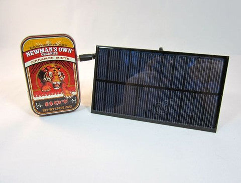
STEP 2: Of Tins and Solar Cells
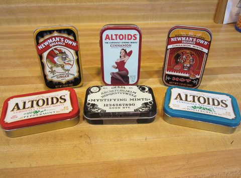
Most people seem to enjoy putting these types of projects into mint tins. Tins such as Altoids are a perfect size for this project. I also enjoy the stylish designs of Newman's Own Organic Mints. You can also find blank tins off eBay, or fun Maker tins over at the Maker's Shed. But the point here is that you pick an enclosure that works for you. If you want a more rugged enclosure you may wish to go with a hard plastic enclosure, or even one that you can make a bit water proof. It all depends on your needs.
For this project I'll be using a Newman's Own Organic Mint tin in the flavor of Cinnamon.
Now about solar cells. For this project we're going to be using a good sized solar cell. If you want to use a small solar cell that fit inside a tin, check out my Solar USB Charger instructions. Same idea, smaller cell, smaller cost.
You want to choose a solar cell that is more than 5V of power and more than 200mA of current. Keep in mind that solar cells are rated at their peak output, not their average output. This means that whatever solar cell you use you will probably never get the output it's rated for.
Also keep in mind that you probably don't want to go over 400mA of current. Throwing too much current at the internal AAs will cause them to die on you. (Unless you want to use 4 AAs, but I'll talk more about that later.)
For this guide I'll be using a 5.5V 320mA solar cell. The current on the solar cell is probably pushing the limit of what my batteries can handle, but from the dozen of these that I've made and given people I've not had a single battery failure.
(To play it safe most people recommend that you don't throw in more than 10% of the current rating for the batteries you use. Meaning, if you have a 2000mA battery setup, you don't want to throw more than 200mA at it. The 10% rule. As solar cells NEVER get their amp rating in a circuit, you can go a bit above without having too much worry.)
You'll also see in the above picture a second solar cell rated at 6V 240mA. This cell also works quite well. Keep this in mind though. The higher the voltage your solar cell has, the less sunlight you'll need to get the batteries charging.

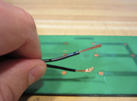
STEP 3: Strip the Wire
Finding a 2.5mm Male Jack with a good length of wire on it is very important to this project.
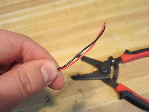
If you look at the wire you'll notice that there are in fact two wires hooked together. One is all black, and one has a white strip along it. The all black wire isPositive, and the white strip wire is Negative.
You'll first want to use some scissors or wire cutters to split apart the two wires. Just a little bit. Don't pull them apart too much, as this makes things more difficult later on.
Then use some wire strippers to strip the plastic coating off of them.
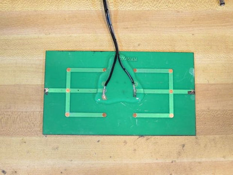
STEP 4: Solder the Wires and Add Glue
Now just solder the wires to their respective spots on the solar cell. White strip wire to Negative, and all black wire to Positive.
Again, don't pull the wires apart any more than necessary. Trust me.
Using a Helping Hand type tool makes this a whole lot easier, and if you don't have one, you should really get one.
Once the solder is cool take your Hot (melt) Glue Gun and cover everything with a thick layer of glue. This covers your solder points, and also secures the wire. You could also use Silicon Calk or even electrical tape, but I find that Hot Glue works quite well.

STEP 5: Drill the Tin
Whether or not you're using a tin for this project, you're going to need some holes drilled.
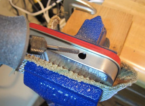
To drill my tin I used a regular drill with a regular wood drill bit. I choose a drill bit that was about the same size as my 2.5mm Female Plug. If you can, start with a smaller drill bit and work your way up.
I also used a vise grip to hold the tin down while drilling. This is not always necessary, but it can be very helpful.
When drilling into a tin you need to be careful. Push too hard and your tin gets all bent out of shape. The best advice I can give is to not push hard. Let the drill bit do the work for you.
Once your hole is drilled, check it against the 2.5mm Female Plug. You're most likely going to need to make the hole larger. This is where a Dremel comes in handy, though you can easily just use a larger drill bit and make the hole larger. A file also works.
STEP 6: Cut a USB Opening
There are two ways to do make an opening for USB.
The Quick and Easy
Measure out the width of the USB port, use a tin snip to cut down to the base of the tin. Fold the tin inside.
The More Difficult and Better Looking Way
You can easily get an opening that is just the right size for your USB port, but it takes a bit of effort.
First, put the USB circuit next to your tin and make an outline of it on the tin.
Second, drill a couple of small holes on the inside of your USB outline.
Third, use a file or Dremel to shape the hole.
The Dremel makes short work of this job. Use a vise grip to hold the tin in place. Also be sure to frequently check against your USB port so you don't make the hole too big.

STEP 7: Cut the Battery Pack Wires
Choose a spot between 1/2 to 2/3rd of the way up the wire on your AA Battery Holder. Cut the wires there.
Then strip the ends of all the wires. Oh yes, even the wires you just cut off. We're going to use them.
(Or you could use some other wire as well. We don't need very much.)

STEP 8: Wire Up the 2.5mm Female Plug
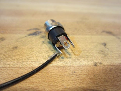
A 2.5mm Female Plug has 3 tabs coming off of it (usually).
Lay it in front of you so that you have all three tabs away from the table, and the tabs facing you. Meaning, the "empty" spot on the plug should be facing the ground.
From left to right the tabs go like this.
Left: Negative
Top: Positive
Right: Don't use this tab.
Bottom: Empty, no tab.
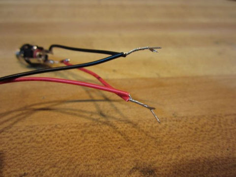
Take the little black scrap of wire you saved from before and hook it around the far left tab.
Grab your 1N914 diode and hook it to the middle, Positive, tab. Notice how on the diode there is a black stripe on one side. That stripe should be facing away from the 2.5mm Plug and SHOULD NOT be connected to the 2.5mm Plug. The black stripe side should then be connected to the red scrap strip of wire you have left over.
Then solder all those points.


Step 9: Connect the 2.5mm Plug to the Battery Pack
And now for a very easy step.
Twist the positive wires from the battery pack and the 2.5mm Plug together. (They should both be red if we followed the directions.)
Twist the negative wires from the battery pack and the 2.5mm Plug together. (They should both be black if we followed directions.)
Now is a good time to have a cup of tea. It's not a necessary step in this project, I just enjoy tea breaks.
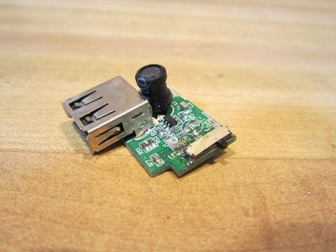
STEP 10: Soldering the USB Circuit
There are many USB boosting circuits out there, but they'll all connect the same way.
Find the spots on the board labeled Positive (+) and Negative (-). All we have to do now is solder the wires onto those spots.
For this I'll be using a Helping Hand type tool.
My advice is to not put too much solder on. Some people seem to go overboard with solder. It's not necessary.
Also, I find it's helpful to take the bare ends of the wire you twisted together, and fold them over once. Often they're way too long and unruly, and this also gives you a larger surface area to solder onto.
*** If your'e using one of my kits, or a USB Circuit that looks like mine, you should do two things before soldering.****
1) Cut off both LEDs from the circuit board. They're useless. Even the white LED is useless as a flashlight. Your cell phone gives off more light. (No, you won't cause a short this way.)
2) You'll see a small switch on the side. It has three positions. Move the switch all the way to the back. Towards the + and - terminal posts. Away from the USB port. This sets the circuit to "Charge" mode, where we want to leave it.

STEP 11: Add Some Tape
If you're using an enclosure that has a metal surface, follow this step. If plastic, don't bother.
Add some electrical tape to the inside of your tin where your USB circuit will be. This insulates your tin to prevent any short circuits from happening.
Adding some below your 2.5mm Plug isn't a bad idea either.
Additionally, some commenters have proposed using other products to insulate the inside of a tin, such as a sealer. This works too. Tape is just the easiest way.

STEP 12: Test It Out!
Before doing any glueing, test out your setup. Add in some regular batteries, or rechargeables, and see if it works. If the circuit does not work, you have a problem.
1) Are your batteries dead?
2) Is the circuit set correctly? (Is the switch in the right place? If using a different boosting circuit, is the voltage set correctly?)
3) Are solder points good?
4) Did you get the positive and negatives hooked up right?
If Your Circuit Is On Fire
You may laugh, but this happens to me every now and then. Even after making over 500 of these things. If you smell burning, or see smoke, take the batteries out ASAP! You have a short somewhere. This is especially true once everything is inside the tin. If not properly insulated you can have a short happen and things can start to smoke.
When your batteries are out, inspect your circuit and solder joints. Most of the time your project will be fine, the components are tough that way.

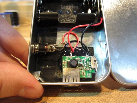
STEP 13: Glue It Down
First, test to make sure everything fits where you want it to. Screw the 2.5mm Plug into place, pop the AA holder into place, get the USB circuit in place. If everything fits well, then glue.
And to be honest, just use Hot (melt) Glue. Double sided foam tape also would work.
When using glue, put a small amount down under the USB Circuit. Hold the circuit down, and wait for it to cool. Then add a bunch of glue on top of the circuit and the solder points. This will help protect them from shorts and moisture.
When finished, add batteries, and you're done.

STEP 14: Variations
The nice thing about this project is it's adaptability. You can easily swap in parts from anywhere.
You can easily add a suction cup to the back of the solar cell, or velcro, or even a snap. This allows you to mount it on a backpack or a window for easy of use.
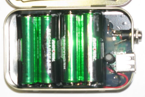
One customer of mine who does mission work in Africa needed a lot of standby power. He choose to use 2 AA Holders and 4 AAs hooked up in Parallel. This doubled the amount of available charging time. To fit everything in he put the 2.5mm Plug up front next to the USB port. You can see his handy work in the picture above.
You could also build a small solar cell array if you have a bunch of smaller cells around. Or even use more than one 2.5mm Male Jack and have several solar setups to pick from. The plug in action makes this easy.
If you're an iPhone user you could use a boosting circuit that has a built in iPhone/ iPod dongle. While this does limit you to only Apple gear, it also saves you from carrying around a cable.
If you want to make this project very small, you could use AAA batteries and a small Altoids Gum sized tin. Or a Dilbert Tin if you can find one.
STEP 15: Enjoy!
And thats the project. Charge up your iPhones, GPS Units, Kindles, Phones, or whatever.
The thing I enjoy about this is that you can charge up your batteries during the day, and then disconnect the solar cell and take the tin with you at night. Or out hiking. Or just leave it in your office for the times when you forget to charge up.
This is a great project for people who want to build something practical. Something you can use every day. It also makes a really nice gift for a gadgety person in your life.
If you do make this project, please post photos of your finished charger.
Again, if you need the parts or would like one of these chargers made for you, visit my little website. 49% of all profits go into doggie squeaky toys.
*** Update. I'm no longer selling this kit or a finished version. I do have a basicSolar USB 2.0 Kit and a more hard core Lithium Heavy Duty 2.0 Kit. If you're looking for something premade you should probably just grab a Folding USB Solar Cell. They're more powerful than this project ever was and at the same price.
 Here is a PDF with more pictures on how to make this Heavy Duty USB in a tin: Heavy-Duty-Solar-USB-Charger-In-a-tin.pdf